

The ISC and the VOC are the maximum current and voltage that the solar cell can generate. The key parameters that define the curve are the solar cell’s short circuit current, ISC, its open circuit voltage, VOC, and the point where the solar cell’s power output is a maximum, the maximum power point, MPP. The p-n junction exhibits an inverse diode characteristic.
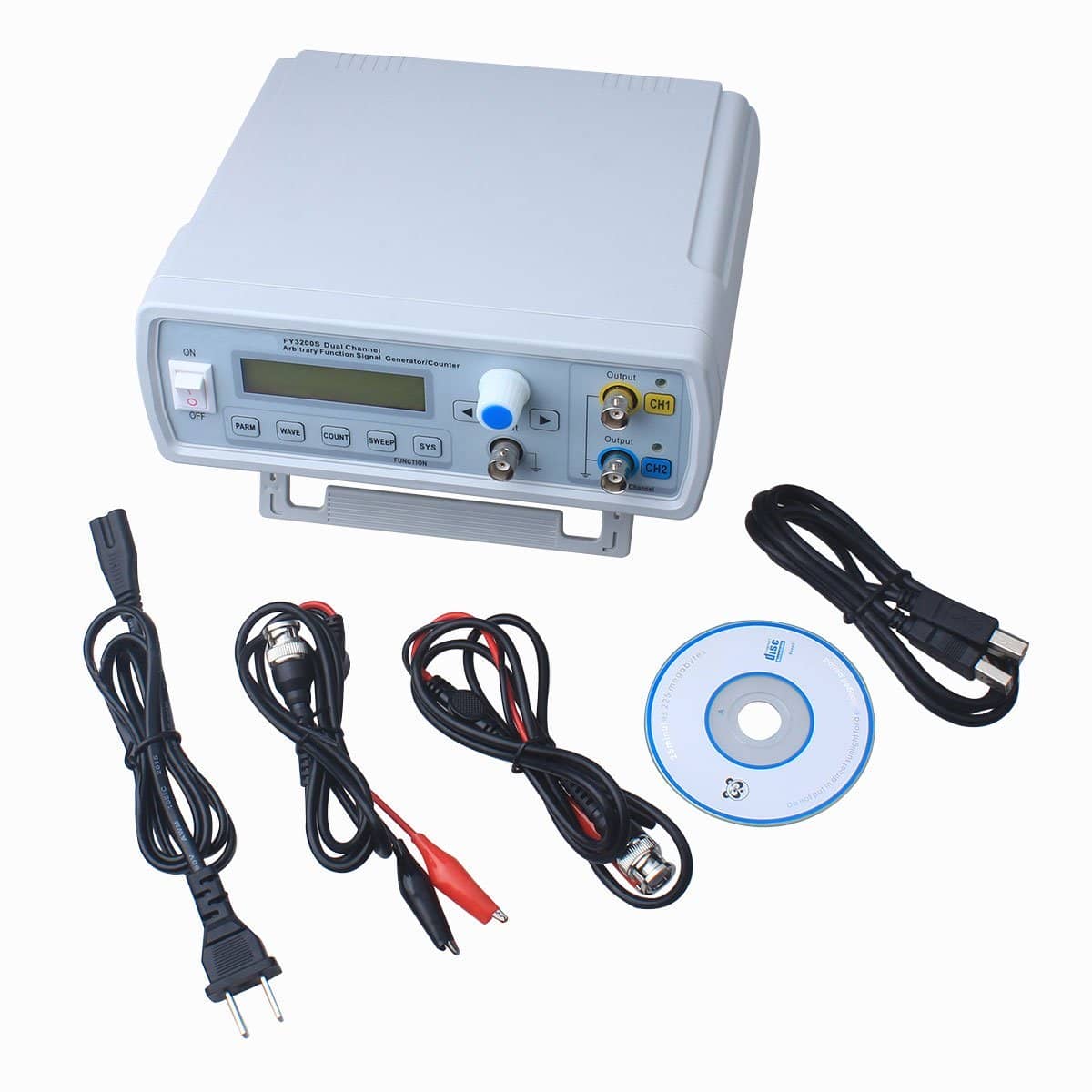
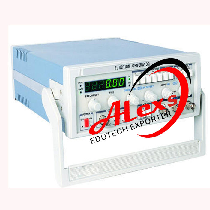
FUNCTION GENERATOR SERIES
Having a lower series resistance and a higher shunt resistance increases the efficiency of the solar cell.īased on this model, the solar cell has an I-V characteristic as shown by the red curve in Figure 3. The shunt resistance represents the insulation resistance defined by the leakage current through the p-n junction. The series resistance represents the resistance of the solar cell semiconductor material and the resistance of its metal contacts.


The series and shunt resistances represent the losses in the solar cell. Figure 2 shows a simple model for a solar cell. The electric field that builds up turns on the diode, and current flows to the output of the solar cell. Photons impinge upon electrons in the p-n junction and provide sufficient energy to enable the electronics to transition to the conduction band. A solar cell model consists of a current source which represents the solar light creating current, a p-n junction represented by a diode, and resistances in series with and in parallel with the p-n junction.
FUNCTION GENERATOR GENERATOR
First let’s review how a solar cell works so we can understand what the function generator will define for the solar panel, a set of connected solar cells. We need to create an I-V curve for the solar panel. Simulating a solar panel or a solar panel array for inverter testing The function generator has the capability to create I-V curves to simulate devices such as solar cells, batteries, and fuel cells. More extensive testing improves product reliability.ĮA’s built-in function generator has even more capability. These are just some examples of how an arbitrary waveform generator built into a DC power supply can conveniently enable a test engineer to more thoroughly test a circuit or a product. Test a circuit’s susceptibility to a kHz custom noise signal representing the output of a switching power supply.Simulate voltage spikes to test a circuit’s level of protection from voltage transients.Determine the range of rail voltages over which a circuit will remain powered.Test a circuit’s response to varying voltage rail ramp-up rates.Test a circuit’s susceptibility to power line noise immunity by adding a 60 (50) Hz signal (and harmonics) onto a DC voltage representing the DC rail lines.The function generator can generate sine waves, triangular waves, rectangular waves, ramps, as well as custom waveforms. In fact, there is no low power hardware to protect as the EA function generator is entirely firmware. Then you do not have to worry about protecting a low-power signal generator from a source of high power. The best solution is to do what EA Elektro-Automatik does which is build the function generator into a power supply or a load. A bias Tee combines a signal generator output with a DC power supply output, but is power limitedīuilt-in function generator for AC + DC signal generation Neither of these options solve the challenge of combining a low power AC signal with a high-power DC level.įigure 1. Most power amplifiers do not amplify frequencies down to DC. Another alternative is a wide band power amplifier that that has a bandwidth down to DC. If you are testing a solar panel inverter, an electric vehicle battery and vehicle circuits, or any circuit operating at higher than 100 VDC, then a bias tee with 100 V and 7 A capacity is completely inadequate. That is a simple connection, but the problem is you will be hard-pressed to find a commercially available bias tee that can pass more than 700 W with a maximum voltage of 100 V and a maximum current of 7 A. You could use a bias tee to connect an AC signal generator and a DC instrument together. One option is to combine the two instruments. The solution requires a combination of a DC power supply or a load and a signal generator to modulate the DC power device. How susceptible is circuitry to noise on your DC rail lines? How can you test the maximum power point tracking performance of an inverter? How can you use instrumentation to meet the dynamic test requirements for electric vehicles? These are just some examples of the challenges that you face when developing test routines to verify the performance of your products. EL/ELR Regenerative & Conventional Electronic Loads.


 0 kommentar(er)
